Centerboard
On this page features of MathML standard are used. Currently it’s practically supported by Firefox and Safari browsers only.
The centerboard of SCAMP can be shaped two different ways. The easier way is to use a flattened foil when thickness is chosen to be 33 mm. More challenging way is to shape the centerboard according to NACA 008-34 foil when the thickness has to be greater, possibly 36 mm. True foil improved hydrodynamics of the underwater parts that presumably makes the boat bit faster. There is also a separate centerboard and rudder kit available that would save you from the joy of shaping.
I chose the flattened foil with thickness of 33 mm. A combination of 12 mm + 9 mm + 12 mm plywoods seemed like a good way to go.
Cutting the pieces
Lofting the centerboard was the very first part of the project. For drawing the first plywood sheet I used a 120 cm square, an ordinary ruler and self-made cardboard molds for drawing the circular corners. This concept worked fairly well, although a smaller and more agile square would be handy in addition to the big one.
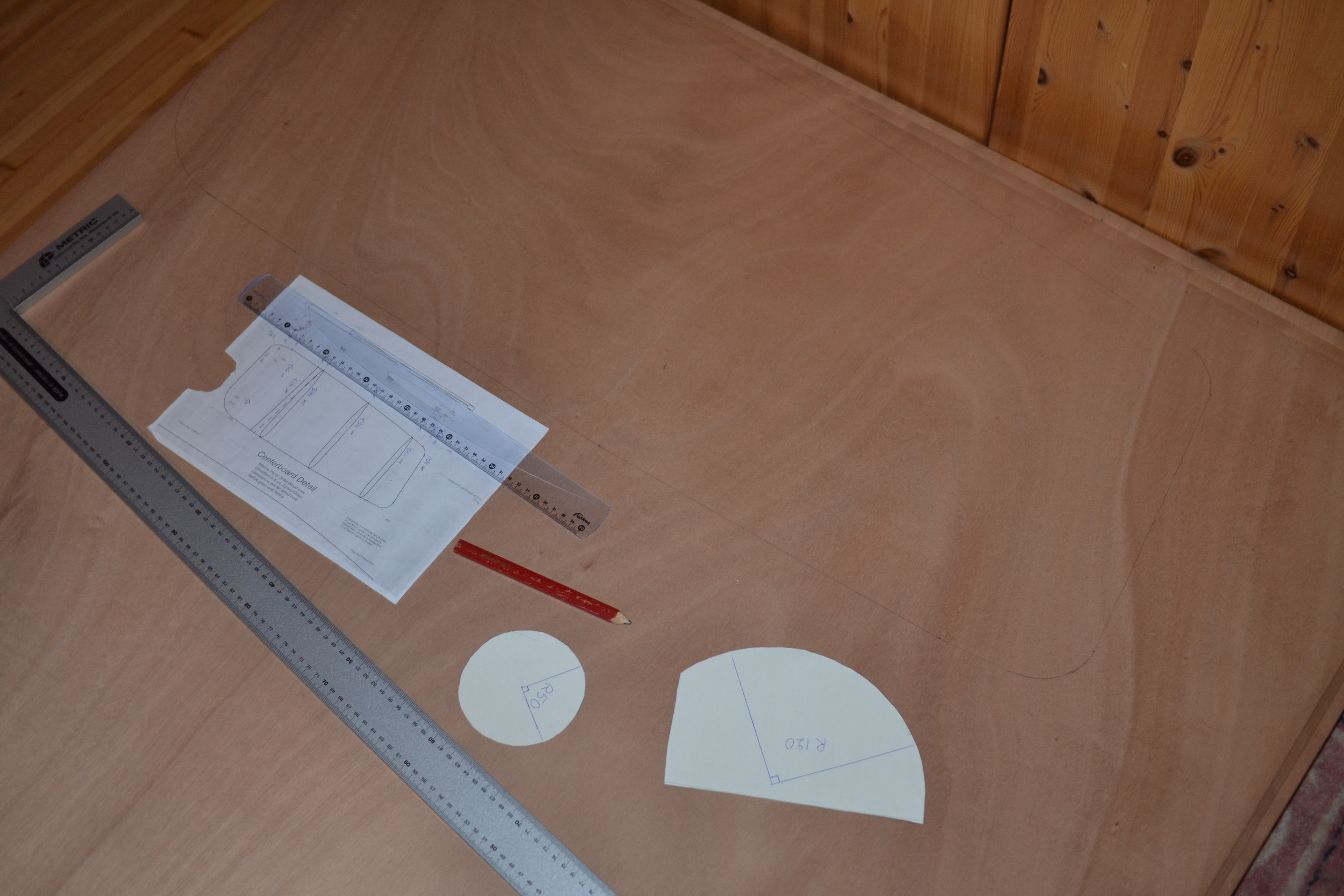
Cutting the centerboard was smooth with Makita 4351FCT saw and BR-13 blade. The quality of the result wouldn’t be that critical because during the NACA foil shaping process you can sand the remaining bumps away. I used the first centerboard sheet as a template for the two others.
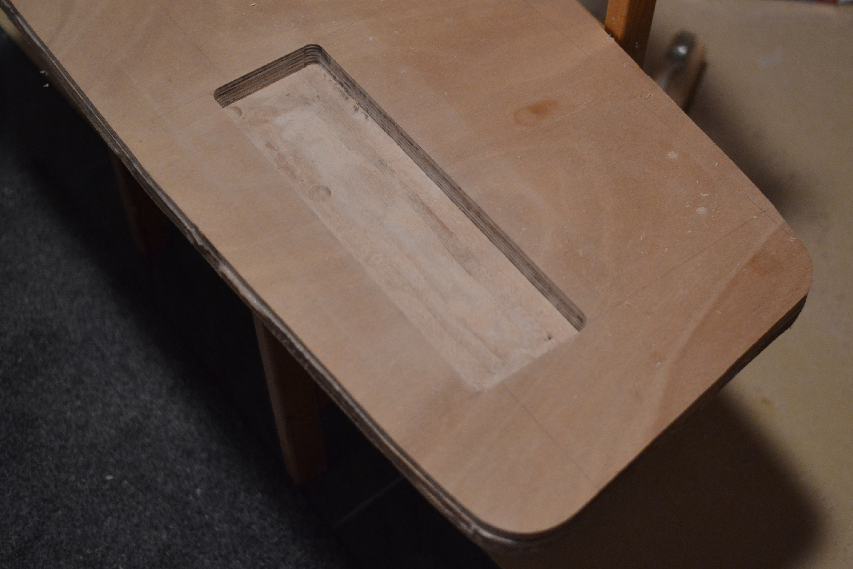
I made a cavity of 380 mm × 110 mm into the centerboard. I planned to cover the cavity with a top lid of 6 mm. The cavity floor thickness is 6 mm. That crops the ballast thickness to 21 mm.

When thinking of the dimensions and position of the centerboard cavity, it seemed best to follow the manual and the plans as closely as possible, although information in them wasn’t without contradictions or inaccuracies. Position relative to the pin and weight of the lead ballast affect to the torque of the centerboard. I tried to make the hole as deep as possible to minimize its area.
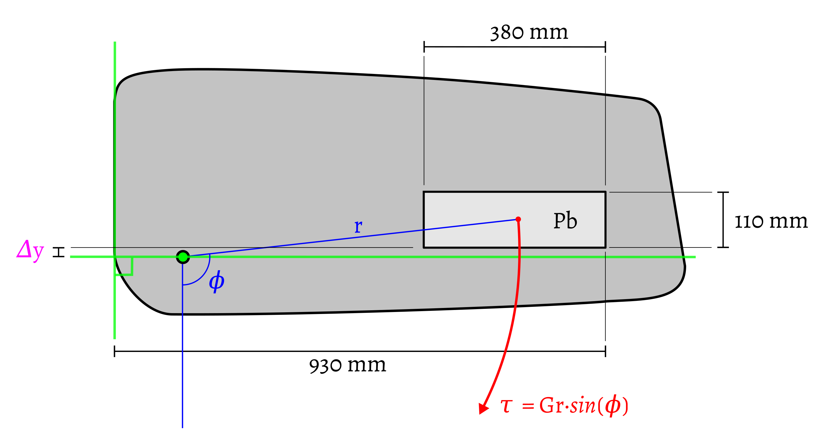
By comparing gravitational force of the ballast and drag force of water, the offset 𝛥y of the centerboard ballast was chosen to be at -20 mm. In the picture positive y direction points upwards. The detailed analysis is available in Finnish only.
Assembly
So, the centerboard is made of three plywood pieces that had to be glued together with epoxy. The glued area was relatively large that meant a good amount of ingredients had to be mixed.
There were three options how to embed the lead ballast into the centerboard.
- to cut a hole through the centerboard and then fill it with bottom cover, lead ballast and top cover
- to route a cavity in centerboard, fill the cavity with molten lead and finally cover it with a plywood lid
- to cut the lead bar into slices and route smaller cavities for them, that free you from working with molten lead
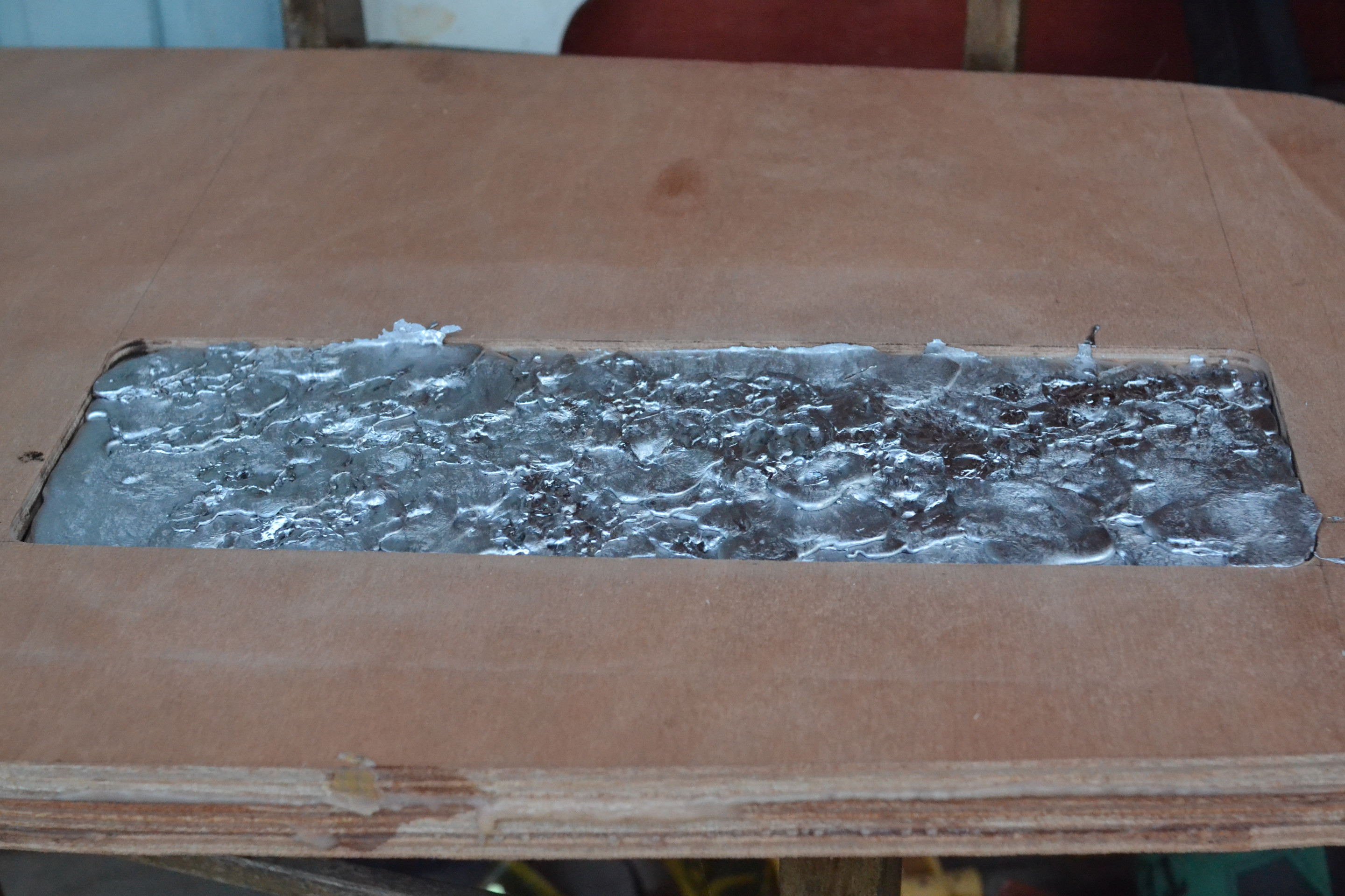
The second option was chose because it seemed the simplest. The cavity was routed with a 20 mm bit to 27 mm depth.
Lead cast
Casting lead is hazardous because of fumes, produced by heating, and possible splashes. Lead is a strong poison which can cause various illnesses or even a death. The Finnish Institude of Occupational Health has information on lead poisoning on their website. I don’t recommend anyone doing a lead cast.
I melt and cast the ballast lead outdoors by a field in windy weather, taking into account the wind direction when positioning the gear needed for the cast. In the beginning I used a gas-powered camping cooker but it turned out to be ineffective, as lead melting point is at 327°C.
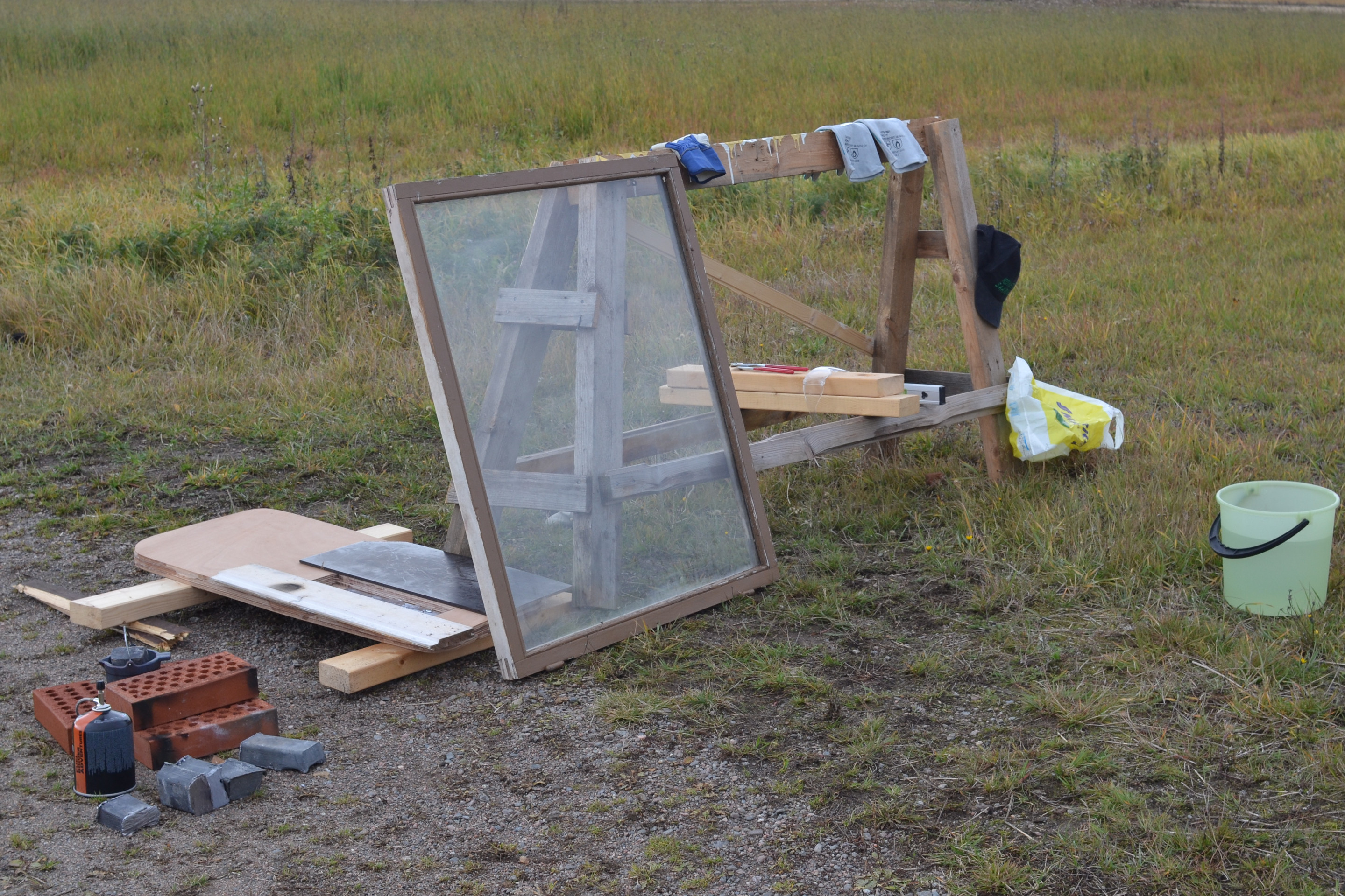
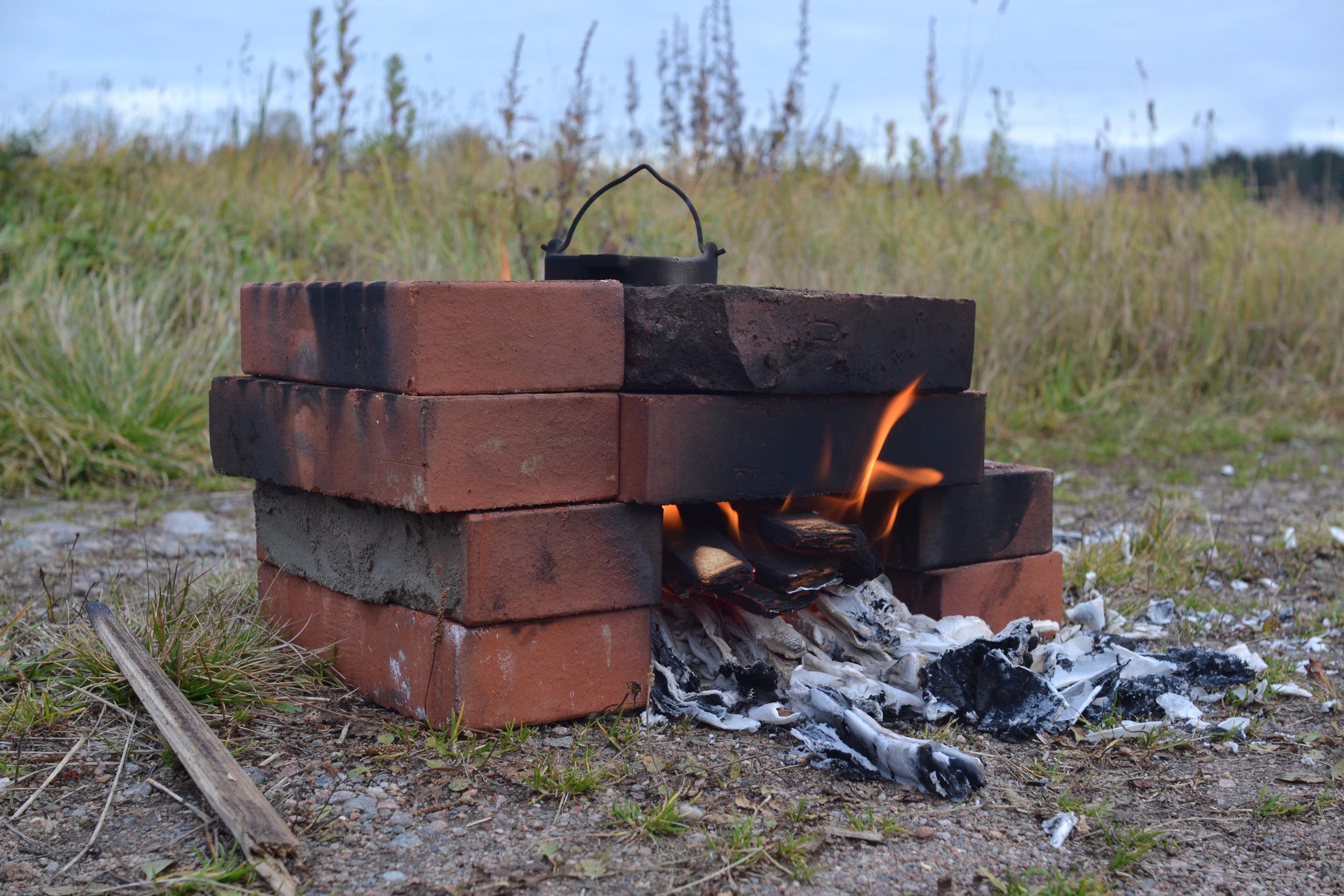
The plan B was to build a small melting furnace of bricks. It provided enough heat to melt lead in around 20 minutes. Brownell’s Lyman 10 lb. cast iron lead pot was used as a cast pot and it was moved by using pliers. The fire stained the pot with soot but that didn’t matter as the pot has only one use.
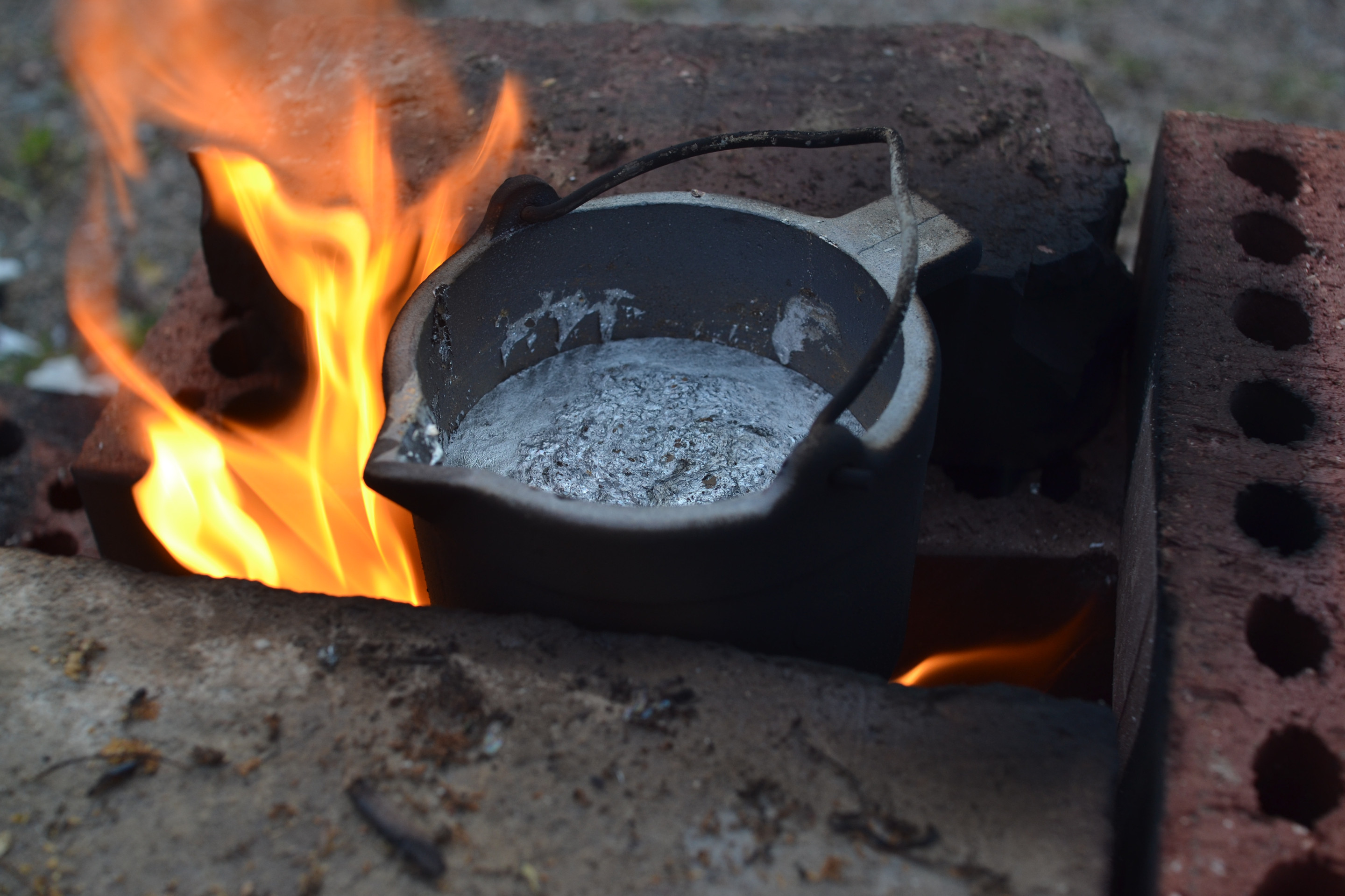
Bit before the sunset I finished the casting. Because the lead was melted and casted in small batches the result reminded bit of the face of the Moon. The weight of the cast is probably a bit more than the planned 10 kg.
Fortunately you don’t need to work on lead more often. Perhaps next time I’ll use small lead shots or iron bits glued together instead of a lead cast.
NACA foil
For the centerboard a flattened NACA 0008 foil is used. It can be found on the plans drawn at a scale of 1:1.
To route the profile I made a driver routing jig. It worked quite well in case of centerboard tailing edge but making it symmetric turned out to be tricky. I had to lift the jig with folded papers to prevent the tail from becoming too thin.

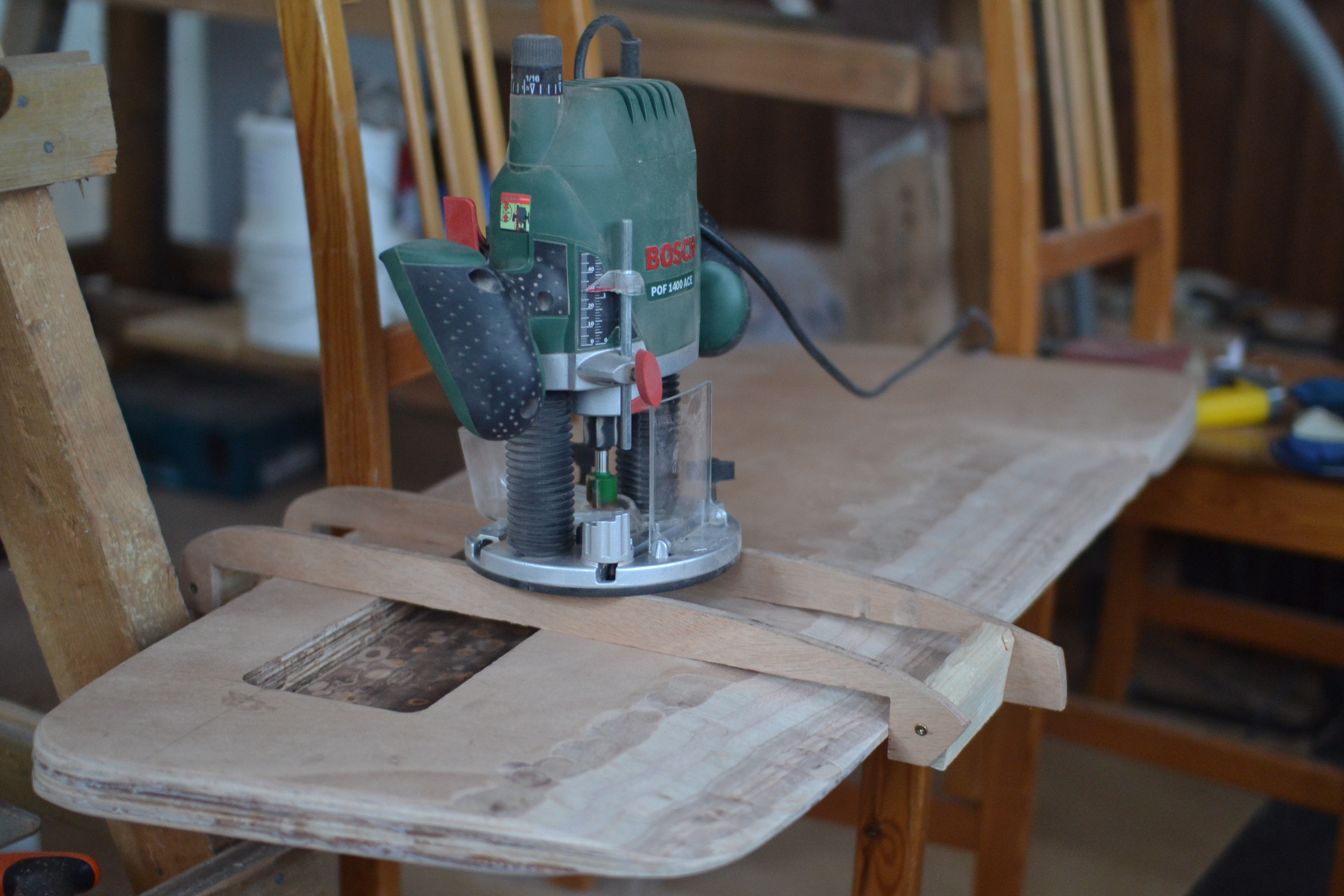
Routing the centerboard leading edge was too inaccurate. I introduced a new more laborious plan to route foil head with steps that were sanded smooth. Ellipse was chosen to approximate the flattened leading edge. Its formula is shown below.
Variables x and y are coordinates from the origin of the ellipse but that’s quite inpractical for routing. We express x with the following formula where i stands for distance from the head of the centerboard.
Also y is expressed with a formula where j is routing depth.
As result we can write the ellipse formula to a different form with variable i is solved.
In the following table there are numbers computed for routing. As the centerboard thickness is 33 mm variable b is 16.5 mm. On the flattened foil the leading edge extends about 60 mm towards the tailing edge, so we decided that a is 60 mm.
| j | i |
|---|---|
| 0 mm | 60.0 mm |
| 1 mm | 39.4 mm |
| 2 mm | 31.4 mm |
| 3 mm | 25.5 mm |
| 4 mm | 20.8 mm |
| 5 mm | 17.0 mm |
| 6 mm | 13.7 mm |
| 7 mm | 10.9 mm |
| 8 mm | 8.6 mm |
| 9 mm | 6.6 mm |
| 11 mm | 3.4 mm |
| 13 mm | 1.4 mm |
| 16.5 mm | 0.0 mm |
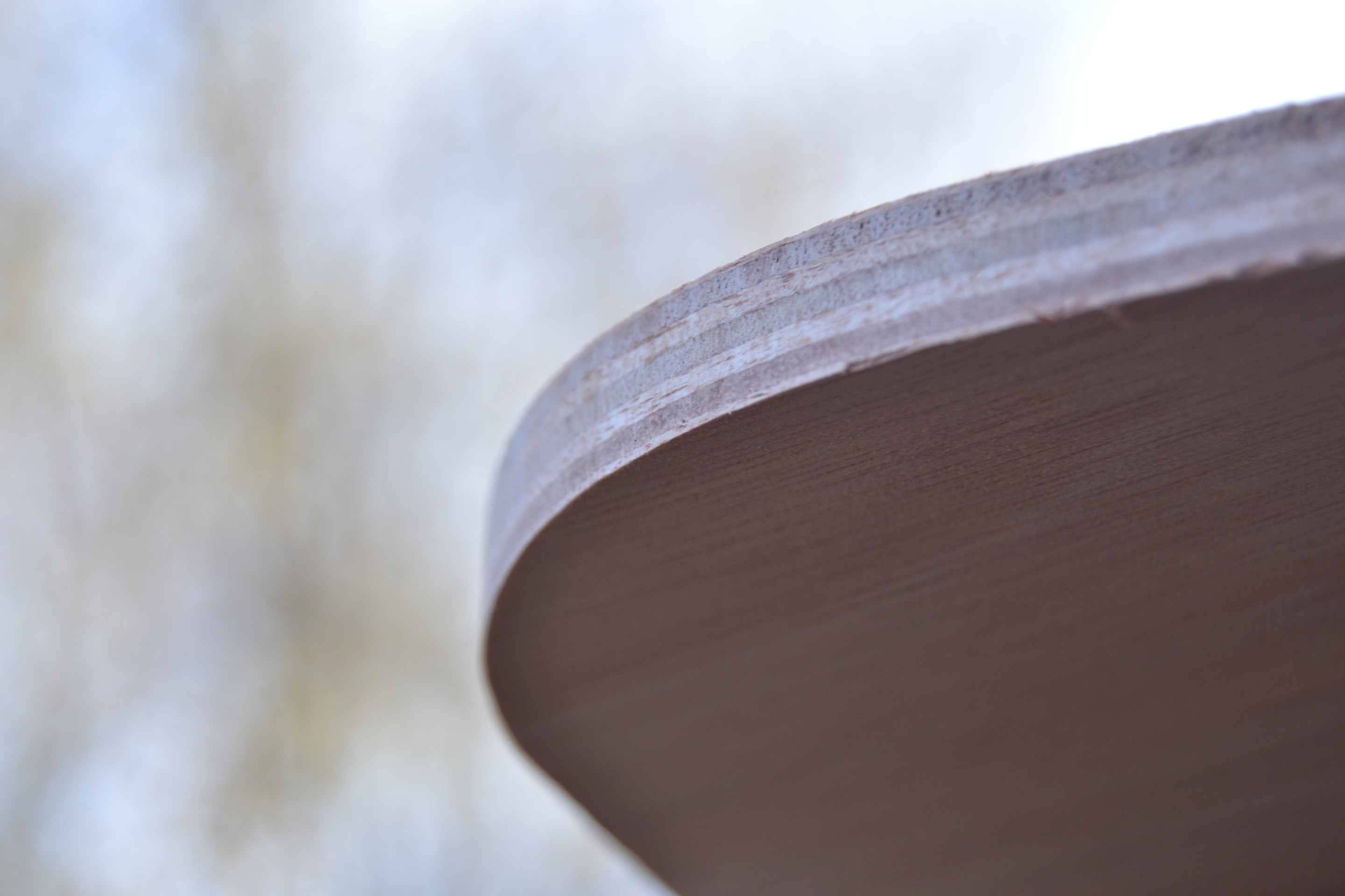
The step profile which resulted from routing looked quite rough but after finishing it looked finer. The slight inaccuracy of routing lines didn’t matter, and then you can hide wrinkles with epoxy.
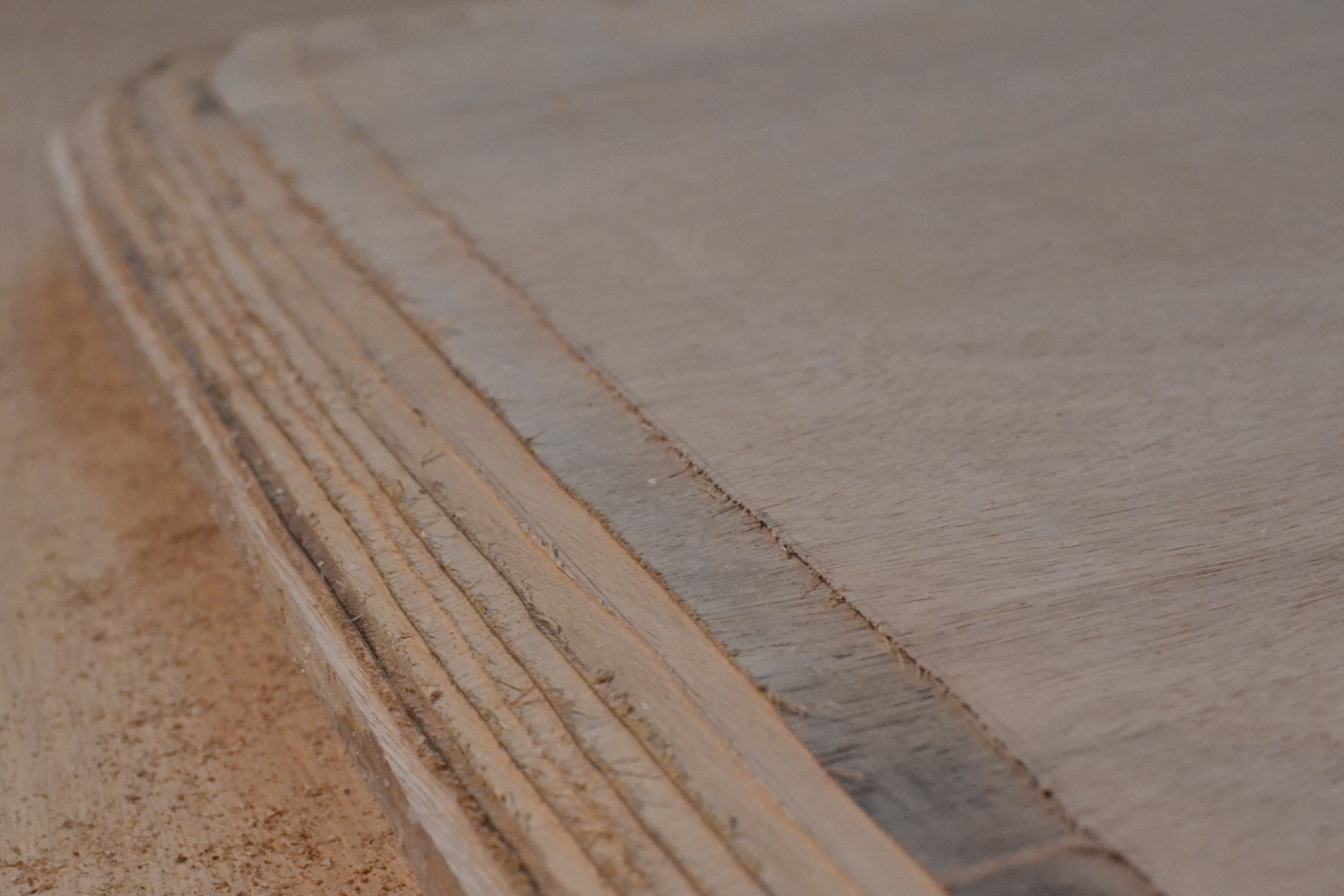
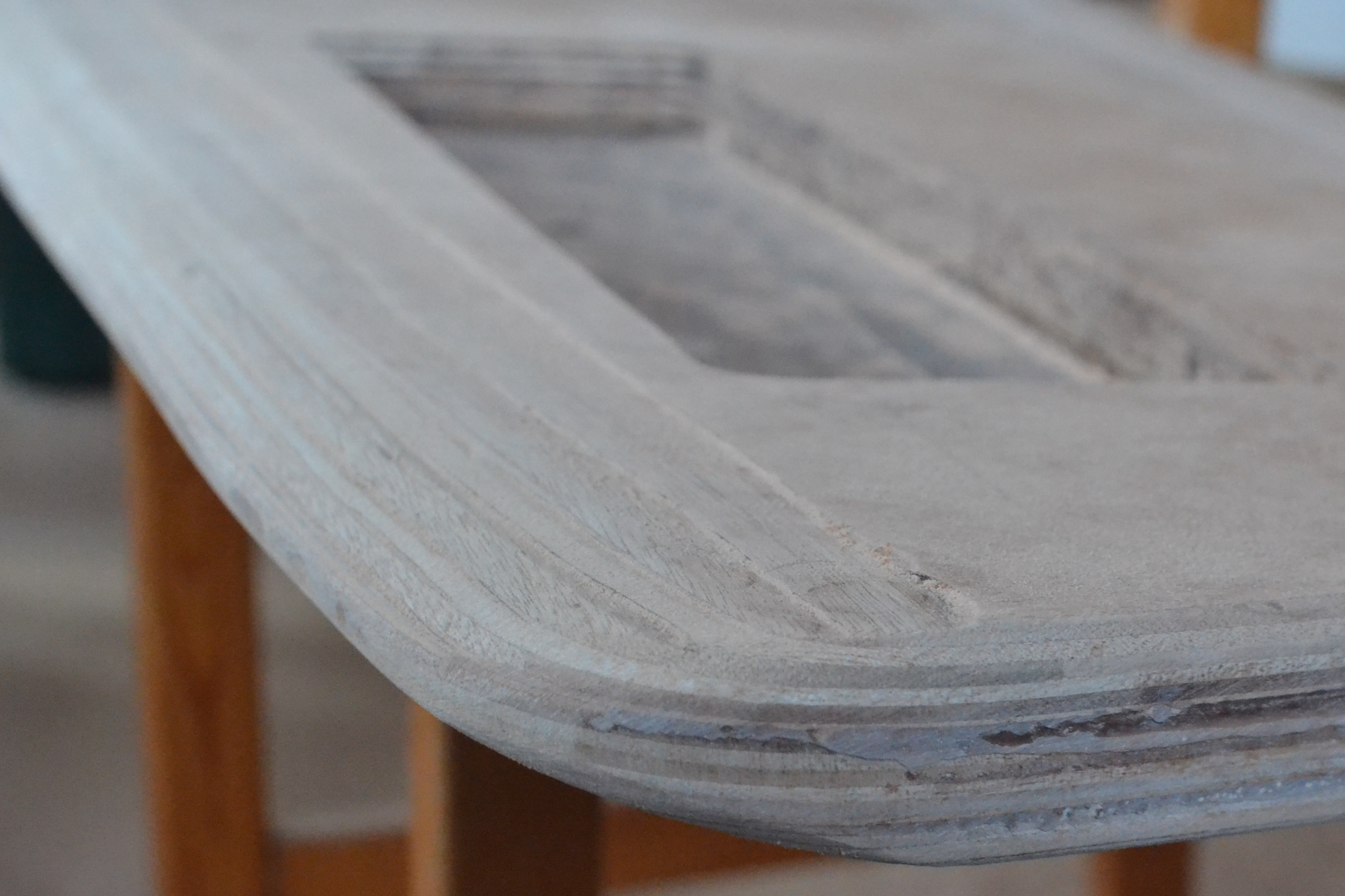
When you compare the leading and the trailing edge you can see that the trailing edge is smoother but the leading edge has more accurate shape. These observations are to be taken in to account when shaping the rudder blade.
Cover for cavity
The original plan was to make a plywood cover over the lead ballast but that didn’t look like a realistic plan because of the bumpy surface of the lead. The cover was made of epoxy which had a maximum recommended amount of microfibers and no silica to keep viscosity as high as possible. An epoxy mix was also used under the lead ballast too to attach it to the plywood on the other side. I chiseled some bumps of the lead ballast to keep it under the surface of the plywood.
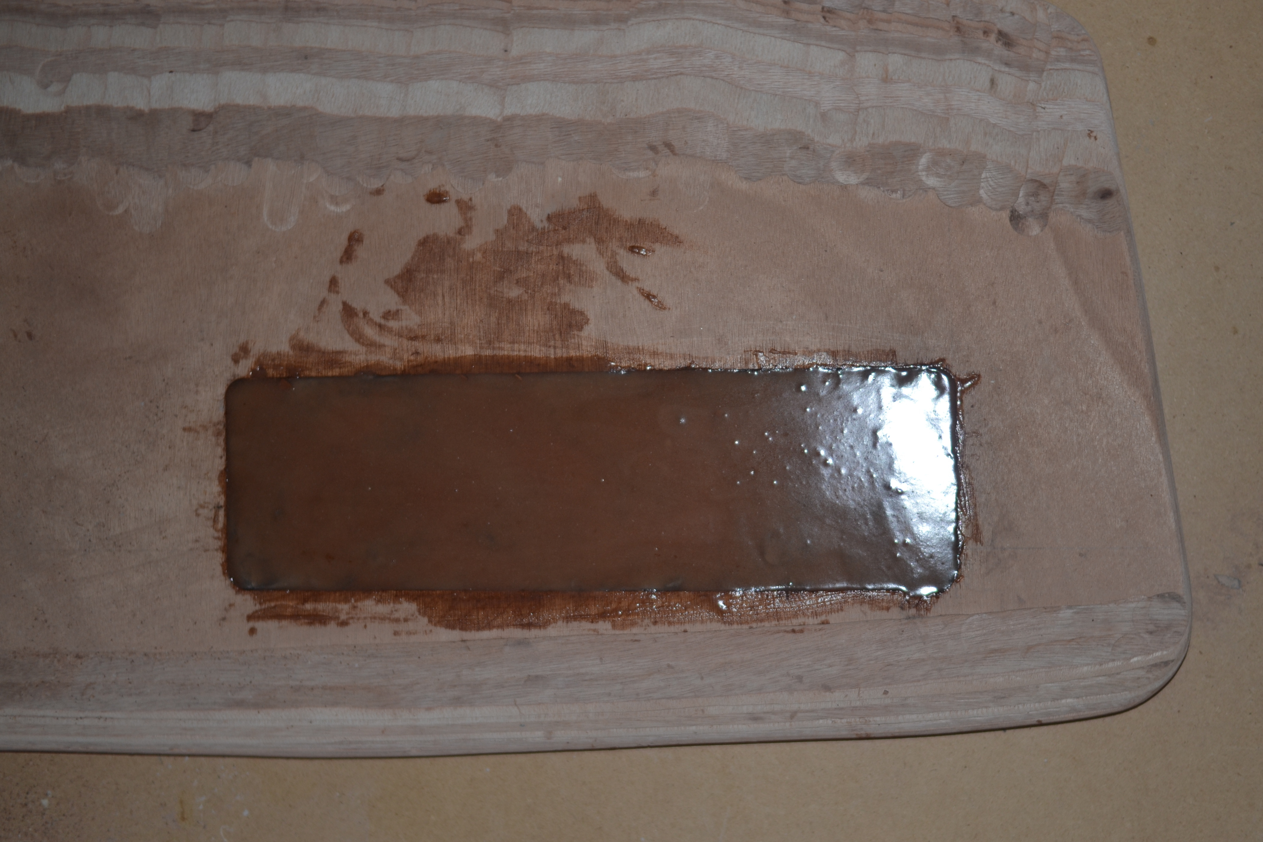
Fortunately the surface of the cover was set a bit, making it go slightly below the level of the plywood. Otherwise the required sanding job would have be quite exhausting. Some sanding was still needed to prepare the cover for another epoxy layer.
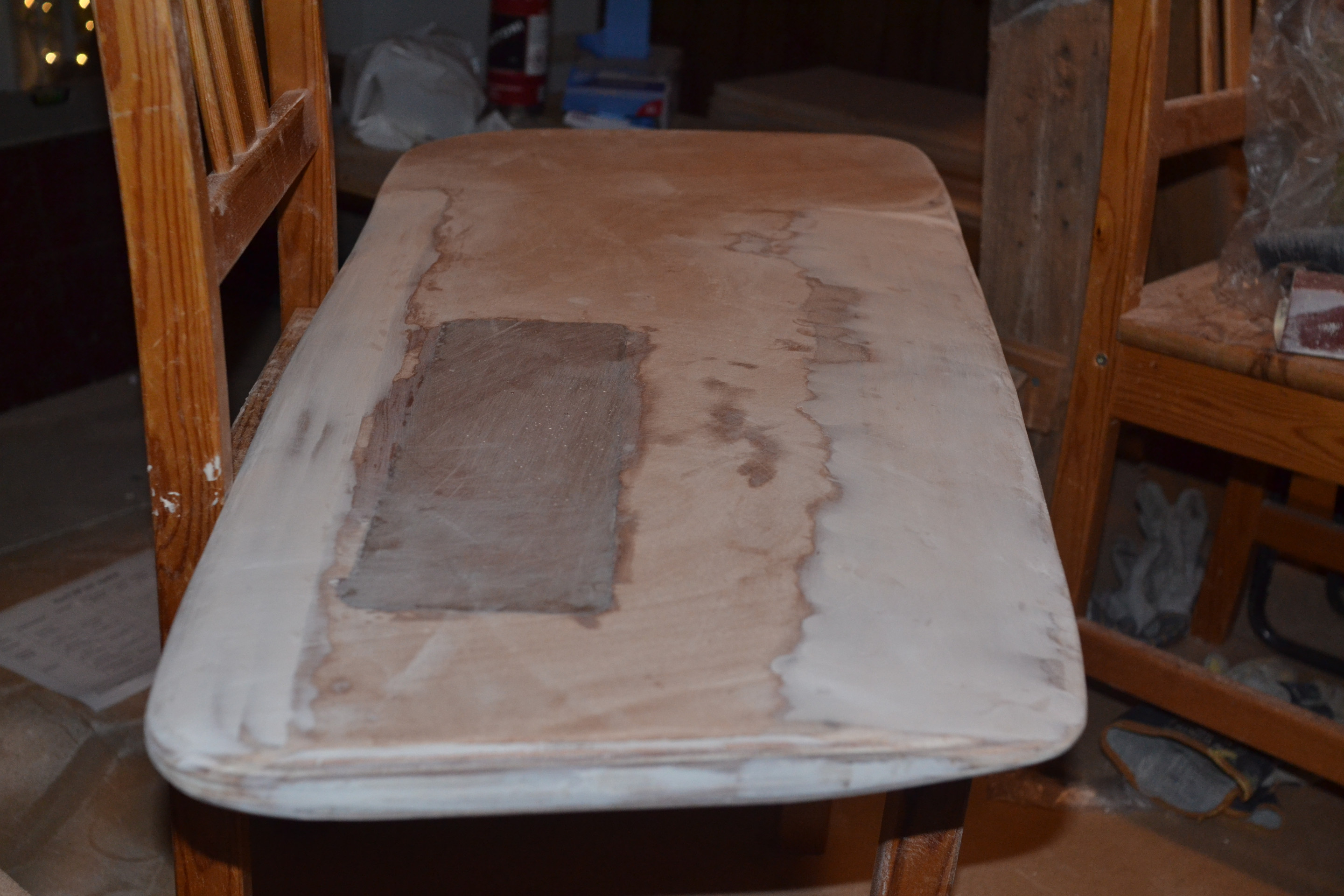
Smoothing and fairing
Routing the NACA profile didn’t reach professional quality on every detail. I mixed two small sets of epoxy to fair roughness of the leading and tailing edge of the centerboard. As fillets I used microballoons. After sanding the result was fairly good.
Fiberglassing
Glassing plywood was a totally unknown thing to me. So, I looked for examples and information from Internet and decided to have first a test with a test piece and a small amount of epoxy without additions. I pressed the fibre onto the epoxied plywood with a piece of ceiling panel. And so, it turned out well!

Glassing the centerboard itself turned out to be a more difficult task than the test piece because centerboard area was bigger and shape more challening.
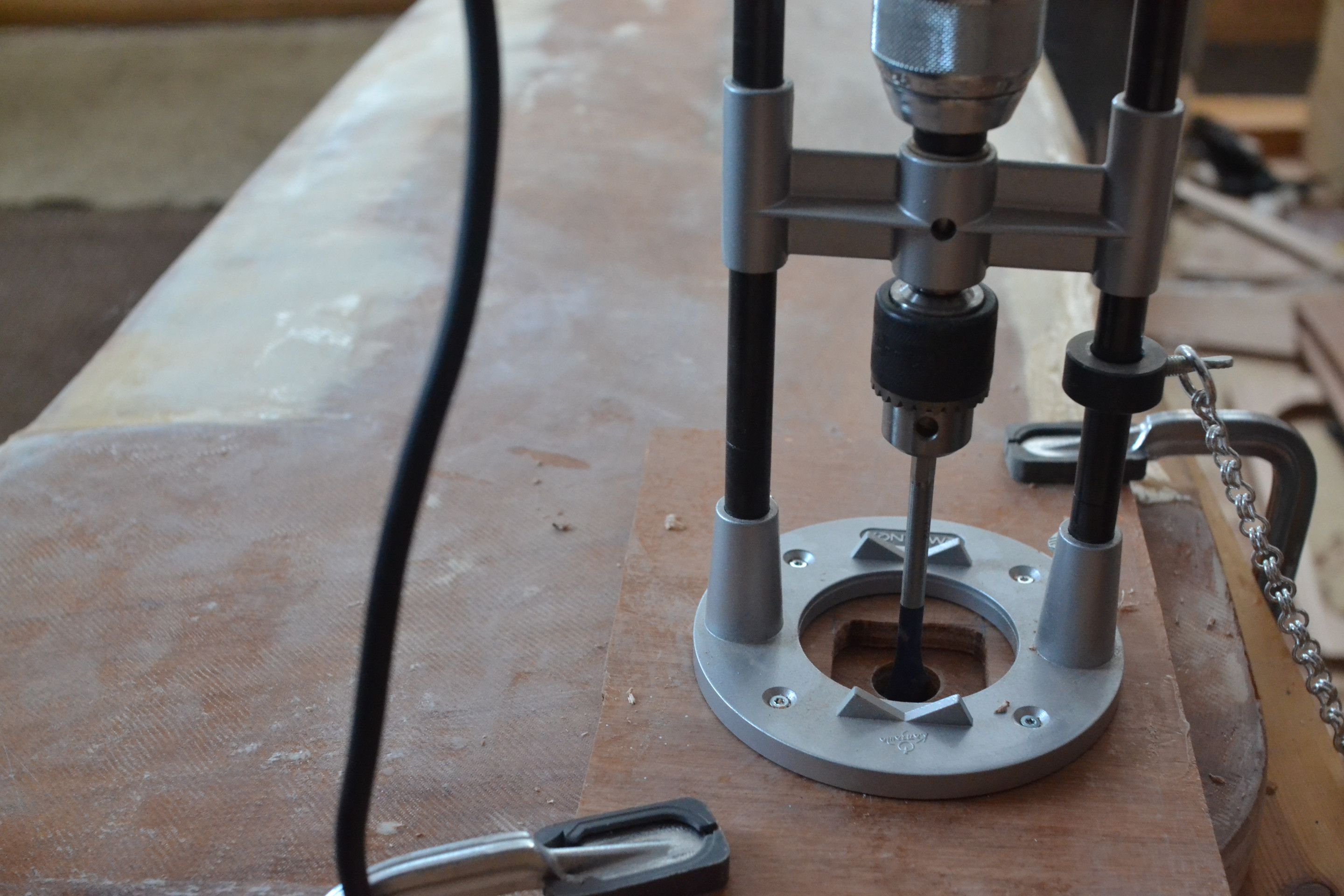
Pivot pin hole
The centerboard pivot (M12) is attached to the centerboard box and the centerboard with bronze bearings (12x18x16 mm). Because an inclinated hole would result problems inside the trunk the hole must be drilled straight. Since I do not own a column drill I used a drill guide (Kanzawa K-801) attached to a plywood piece. The hole was drilled with a 20 mm bit.
Tail loop
When the boat capsizes and if the centerboard is then inside centerboard trunk you have to get the board out somehow to make recovery of the boat possible. As such, a hole was drilled into the bottom near the front of the centerboard. Then a looped line is threaded into the hole. Position of the hole and length of the line has to be designed so that the line doesn’t jam the board in the trunk.
…
Finishing
…
Uphaul line
…
| Next: | Jig |
| See also: |
Centerboard trunk (stage 2) Pivot pin (phase 5) Building Merisirri |